|
INTRODUCTION
BASIC MODULE - THE HEAD
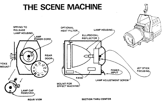
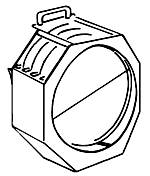
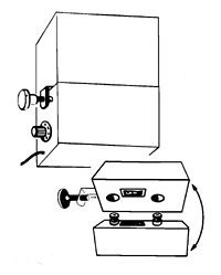
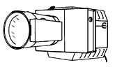
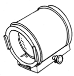
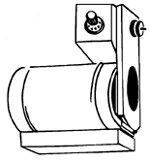
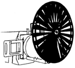
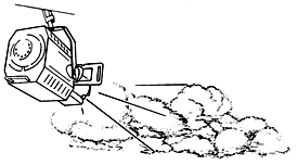
The Projector Head is the basic module of the incandescent Scene Machine. It houses the light source, reflector, fans, heat filters and power cord. The various effects machines slide onto the front of it and are plugged into it. Lenses are then attached to the effects machines. There are two models, the EQS-10, 1000 watt and the EQS-20, 2000 watt.
The Projector Head comes equipped with a yoke for mounting on a stand or hanging from a pipe. No tools are necessary for tightening the machine in position, changing effects machines, or changing lenes.
POWER
The main power cable of the EQS-10 (1000 watt) Projector Head should be plugged into a non-dim circuit only. The projector contains fans for cooling; the fans and motors must never be plugged into a dimmer! There is a white cord with a plug that can be reached by opening the rear door of the projector. This is an independent circuit for the lamp, and can be plugged into a dimmer if required. All of the effects machines will plug into convenient outlets on either side of the Projector Head, toward the rear. They may also be plugged into independent, non-dim circuits.
EQS-20
There are two input cables for the EQS-20, one powers the 2000 watt lamp, the other powers fans and accessories. Separate power cables enable you to plug the accessories and fans separately and not through the dimmer. Like the 1000 watt projector head, there are convenience outlets on either side to power the effects cases. The lamp power supply cable can be plugged into a dimmer and controlled from a conventional dimming system.
HEAT FILTER
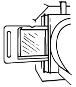
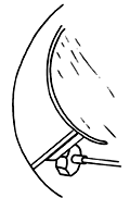
The heat filter assembly in the front of the projector housing contains three elements: two dichroic heat reflecting filters and one split glass heat absorbing filter. Access to it is from the hinged lid on top of the projector. Handle with care! The heat filter assembly must be used with glass and film loop effects. It may be removed when steel effects are being used.
LAMPING AND ADJUSTING THE FIELD OF LIGHT
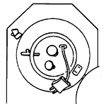
To relamp, first open the rear door of the Projector Head. Release the spring tension device located at the center point on the left-hand side of the lamp cap. Pull the lamp housing out, and replace the bulb. Be sure the lamp is fully seated. Replace the lamp cap. Center the bulb in the EQS-10 (1000 watt) with the round black focusing knob in the center of the lamp cap. The adjustment screw at the bottom of the lamp cap moves the lamp forward and back inside the reflector. For optimum light output, the lamp should be cranked to the farthest forward position with this screw, then two turns back to even the field.
EQS-20
To align the lamp in the EQS 20 (2000 watt unit) there are three adjustment knobs clearly marked. One for vertical lamp alignment, second for horizontal lamp alignment and the third for lamp penetration. Adjusting the optical field of both the 1000 and 2000 watt GAM Scene Machine is very similar to the adjustments of an ellipsoidal spotlight.
HANGING IT UP
The Projector Head may be mounted on a stand, or on an overhead pipe by means of a c-clamp. It can be used at any angle, straight up, straight down, or straight out. The "tungsten halogen compact filament" lamp will give long life in any position. Each effects machine (except the Spiral Machine) is mounted on a rotating turret to give you 360ƒ flexibility.
PUTTING IT TOGETHER
Before attaching an effects machine to the Projector Head, be sure that the yoke is secure. Slide the chosen effects machine into the slots on the front of the Projector Head. Pull back the safety spring on top of the left-hand slot while attaching the machine. Slide your lens into the slots on the front of the effects machine. Again, pull back on the safety spring.
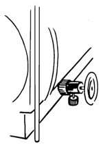
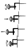
To adjust the focus of the lens, first loosen the small red locking screw on the slide of the lens housing. Then turn the black focusing knob just above it. When focusing is complete, tighten the red screw again.
MAINTENANCE/OPERATION MANUAL:
THE GREAT AMERICAN SCENE MACHINE
HEAT FILTER ASSEMBLY
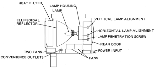
The EQS-10 and EQS-20 housings contain a unique three-element heat filer system. The three glass elements consist of two dichroic filters and one split glass heat absorbing filter. They are contained in a removable heat filter assembly. The largest dichroic heat reflecting glass, approximately 7" in diameter, is placed closest to the lamp with the dichroic coating facing toward the lamp. The second dichroic filter, approximately 6" in diameter, is placed in the middle. The split glass heat absorbing filter, also 6" in diameter, is placed farthest from the lamp. It is in two pieces in order to withstand the high temperatures generated as it absorbs heat from the beam of light.
Should you ever take apart the heat filter assembly, or replace a cracked element, it is essential that you keep the dichroic coatings facing toward the lamp. Remember - the larger dichroic filter goes closest to the lamp, the smaller one in the middle, and the split glass farthest from the lamp. Keep in mind, when assembling the heat filters, that the handle will be inserted toward the lamp. There is a small sliding latch in the housing to hold the assembly in place.
The heat filter assembly must be used with glass slides and film loops, but is not essential when stainless steel effects are being used. In the latter case, removing the heat filters will almost double the light output of the Scene Machine. With the heat filters in place, stainless steel effects will last indefinitely. Without this protection, they may require replacement in time.
The split glass heat absorbing filter is the most fragile element and can easily be broken for several reasons. First, it must be loose in the assembly to allow the expansion. Therefore, in transportation, it has a tendency to rattle and it can chip. You can secure it with a little piece of foam slipped between the two elements to minimize this risk in shipping. When the EQS-10 lamp is focused in a very hot position, the concentrated beam of light crossing at the heat filter can cause it to crack. This should be avoided at all times by proper positioning of the lamp in the reflector. Using the adjustment screw in the lamp cap, crank the lamp to the forward-most position, then two turns back.
When the Scene Machine is first turned on, heat is generated rapidly. Temperature in the gate area will reach 1000ƒ Fahrenheit in short order. If the housing and heat filter assembly have been exposed to cold air, or if there is a draft from an air-conditioning unit, it can cause the heat filter to crack. If at all possible, warm it up gradually by bringing the lamp up on dimmer or turning it on and off for a short period of time (5 seconds) before leaving it on. If the unit has been in a cold building overnight, or off-loaded from a cold truck, warm-up is essential. Painted glass and film loops cannot be used without the heat filter assembly intact. It is advisable to carry spare split heat filters on the road.
FANS
Two fans are mounted in the bottom of the EQS-10, one below the lamp, and one below the heat filter assembly (4 fans in the EQS-20). These fans must be operating and unobstructed whenever the lamp is on. Should the lamp be operated on a separate circuit, care must be taken to insure that the fans are operational before the lamp comes on. Should the fans be inoperative, blocked or obstructed in any manner, it could cause the heat filter to shatter. The fans must always be powered through a non-dim circuit.
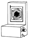
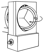
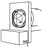
DISC MACHINE (EDM)
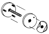
The Disc Machine is designed to be used with the basic Projector Head. It has two modes of operation. First, it is a remote control slide carrier, and second, a case for large stainless steel discs which can create moving clouds, fire, rain, snow, etc. It can be rotated 360ƒ so that the effects may be positioned at the operator's convenience. Rotation is accomplished by means of a spring loaded latch at the top of the machine. Lift the latch and rotate the case to the desired position, then release and allow it to lock in place.
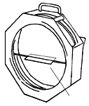
Effects can be changed easily. Open the case (secured by three latches around the side), then remove the locking nut and black hold-down plate. The stainless steel disc is dropped over the inter shaft, hold-down plate replaced and the locking nut hand tightened. The case is then closed, latched, and mounted on the projector head. It can be plugged into the accessory outlet on the side of the housing or powered from an external source. The Disc Machine motor should never be operated from a dimmer as this will cause the motors to burn out.
The Disc Mask Adapters (DM-M1, - M2, -M3) are used to break up the patterns of the projections for rain, snow, and fire. After mounting the Disc Machine on the projector head, gently slide the appropriate Disc Mask Adapter in the same slot that holds the lens.
Speed and direction controls are on the side of the motor box on the face of the EDM. The selection switch should be in the 'disc' mode when stainless steel discs are being used, and in the 'turret' position when the slide turret is used.
The slide turret mounts in the EDM in the same fashion as the stainless steel disc. You will notice a small positioning hole in the slide turret and one in the black hold-down plate. When the turret is in position, be sure that the little plunger comes through the hole, and as you replace the hold-down plate, be sure that you see it in position. Then hand tighten the locking nut in place, close and latch the door.
There is a remote control cable for the EDM to change slides. A two-pronged receptacle for it is on the side of the control box. When the control cable is screwed in place, the control switches should be in the following positions: Selection switch should be in the 'turret' position. Direction should be 'forward'. Speed control should be at '10'. Now, by merely pushing the button and holding for a short count of three, you can rotate to the next slide automatically. Do not hold the button down for too short or long a time, or the next slide will not be properly positioned. The remote control cable is two wire zip cord and can be extended easily by splicing in the desired length of zip cord.
DISC MACHINE/REMOTE (EDM/R)
Operation of the EDM/R is similar to the EDM with the following additional features: A remote control box for all functions is supplied with this unit, along with a 100' detachable cable. The control box can be mounted and plugged directly to the Disc Machine. Hold the control box in your right hand under the motor box on the face of the disc machine. Note the pin plug and mounting studs on top of the control box. Align with the pin plug receptacle in the bottom of the motor box. The mounting studs will fit into the bottom of the motor box when you push the locking plunger (on the side of the box) in with your left hand. Gently but firmly push up on the control box, being sure that the plunger is all the way in. When properly connected the motor box and control boxes will be flush against each other. Now let the plunger out with the left hand to secure the control box. Finally, screw in the locking knob on the plunger to lock the box in place. You may plug the power cord of the control box into the accessory outlet on the side of the projector head or into an external source. To remove the control box, reverse the procedure: Unscrew the locking knob on the plunger. Push the plunger in and gently pull down the control box.
To use the control box in the remote mode, plug the detachable cable to the bottom of the motor box and to the control box. 110 volt power will have to be supplied for the control box wherever it is located. Do not operate the control box from a dimmer, since this would burn out the motors.
To control, set the selection switch in either 'disc' or 'turret' position. Speed and direction controls are provided for use with the stainless steel discs. There is a timing mechanism in the control box for operating the slide turret. When you push the button, the turret will automatically advance.
FILM MACHINE (EFM/R)
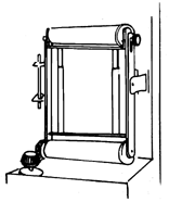
The Film Machine is designed to be used with the projector head. It uses a continuous polyester loop to create moving clouds, rain, fire, and other effects. In addition to using standard loops, you can paint clear loops or apply graphics to film photographically. There are also thin metal film loops designed to be used without heat filters. Stunning effects can be quickly and easily achieved.
The Film Machine has a pattern slot and pattern holder so that the loop can be used in combination with a 4" x 5" pattern or painted glass slide. There are also four framing shutters.
Unlatch and open the hinged front door of the Film Machine. There will be two rollers on an assembly, over which you must slip the film loop. Disengage and swing the roller assembly forward. Be sure that the knob at the side of the top roller is loose. Depress the top roller, which is on a spring-loaded shaft, then tighten the knob so that the roller remains stationary. Then the film loop can easily slide into place. Release the knob, and the spring-loaded carriage will apply the proper tension to the loop. Do not tighten the knob when the loop is in place. Film loops can easily be changed, even when the Film Machine is in operation.
Controls for the Film Machine include direction and speed as well as a high and low gear to further extend the speed control of the unit. The machine can be rotated 360ƒ degrees for convenience of positioning. A spring loaded latch for rotation is located at the top of the unit. Lift up on the latch and turn the unit to the desired position, then release and allow it to lock in place.
The EFM/R has an optional remote control box which plugs into the bottom of the unit. To operate, be sure that the lever on the side of the Film Machine is in 'remote' position, rather than 'manual'.
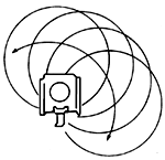
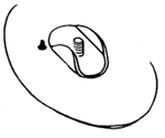
SPIRAL MACHINE (ESM)
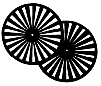
The Spiral Machine is designed to be used with the basic head. It will rotate one or two glass or steel discs which are approximately 6" in diameter.
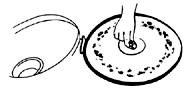
To mount the selected Spiral Effects, place the Spiral Machine on its back. Lay a Spiral Effect on the ring holder. You will see four small tabs that swing over to hold the effect in place. Now turn the Spiral Machine on its face to expose the second ring holder and duplicate the process. Slide the machine into the slot on the face of the projector head. Plug it into the accessory outlet on the side of the housing or into an external power supply. Never plug the Spiral Machine into a dimmer since operating from a dimmer will burn out the motors.
The Spiral Machine has separate speed and direction controls to rotate each disc, located on the sides of the motor box on the face of the machine. The three position direction switches include center off.
SLIDE CARRIER AND MASK (ESC)
The Slide Carrier and Mask is designed to mount on the projector head. It features a hand operated, rotating turret which can be turned 360ƒ. Just lift the spring loaded locking latch at the top and turn the Slide Carrier to the desired position. Release the latch and allow it to lock in place. The double slide carrier holds two 4" x 5" steel or glass slides. It is notched so that when positioning correctly, it cannot slip. When inserting the slide carrier, be sure that the indent notches align with the nylon roller in the turret.
ESC/R
ESC/R Slide Carrier and mask with fan is designed for use with the 1000 and 2000 watt Scene Machine. It slides in place in the same fashion that the standard slide carrier does. It's advantage is that it has a cooling fan and it is recommended for use with photographic transparencies and painted glass slides.
OBJECTIVE LENS (OL- )
There are a variety of objective lenses for the Scene Machine. The Objective Lens is used in conjunction with the projector head and one Effects Machine. The widest angle lens is the OL-3S and the narrowest is the OL-16. There are 10 objective lenses to choose from including both standard and high resolution lenses. The Objective Lens slides into the mounting slots on the face of each Effects Machine. It can only mount in one direction. The forward color frame holder will not fit into the mounting slots, therefore the lens cannot be mounted backwards. The Objective Lens is focused with a knob on one side of the lens housing. There is a small red locking screw under the focusing knob to secure the focus position and to hold the lens in place during shipment. The mechanism utilizes a gear drive for precision focusing.
Should the gear become disengaged because of vibration or rough handling, the shaft can be repositioned by loosening two set screws under the focusing knob. Use an offset Phillips screw driver. After loosening the screws, reposition the shaft firmly against the gear rack and tighten the screws. If the lenses need to be cleaned or replaced, the bottom focusing pan should be removed from the upper lens tube. Four screws secure the pan to the tube. Remove them and carefully rotate the pan 90ƒ to slip the lens assembly through the bottom slot. The lenses are held in place by a spring ring. When re-assembling, remember that the curved surfaces of the lenses face each other with the black ring spacer in between.
FLICKER WHEEL MACHINE (EWM)
The Flicker Wheel Machine is designed for use in front of the Objective Lens. It slides into the color frame slot. The machine is supplied with two flicker wheels and can be used with one or both in place. When both are in place they rotate in opposite directions.
To mount the wheels on the machine, stand the machine up on the edge of a table, motor box away from you. The wheels will slide onto the shaft in the back of the machine. To use one wheel: Remove the locking nut from the shaft. Slide the wheel with the one small hole near the center onto the shaft. Be sure that the tiny plunger in the black holding plate comes through the small hole in the flicker wheel. Replace the locking nut and hand tighten.
To use both wheels: Remove the locking nut and the black holding plate from the shaft. Remove the three screws from the black plate on the shaft. Slip the first flicker wheel over the shaft with the rolled outer edge facing away from you - be sure it is the wheel with the three holes for the screws. Align it so that the indents in the center hole fit over the tiny rod on the shaft, then turn to align the screw holes with those on the black plate. The wheel should be flush against the plate. Replace the three screws and hand tighten, then replace the black holding plate, flat side towards you. The slot in the back of it should fit over the tiny rod on the shaft. Then place the second wheel on the shaft as described above, with the rolled edge facing toward you. Replace the locking nut and hand tighten.
The Flicker Wheel Machine mounts on the Objective Lens upside down, with the motor box above the lens and the wheels in front of the lens. If it is more convenient, you may mount the wheels on the shaft after placing the machine on the front of the lens.
Plug the Flicker Wheel Machine into the accessory outlet on the housing or use an external power supply. Do not plug it into a dimmer, since operating from a dimmer will burn out the motors. Speed and direction controls for the machine are on the motor box.
The flicker wheels should be handled with care when they are mounted, stored or transported, as they can easily be bent.
KALEIDO MACHINE (EKM)
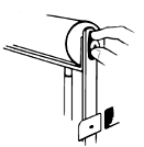
The Kaleido Machine is designed to mount in front of the Objective Lens and rotate a 6" diameter prism front to back. It is supplied with a removable prism, (three or five faceted). To install the prism, rotate the black ring holder so that the retaining tabs and screws face you. Lay the unit on its back and place the prism, flat side down, on the ring holder. Swing the retaining tabs over the prism rim and hand tighten the screws. Slide the Kaleido Machine into the color frame slot on the front of the Objective Lens. You may plug the power cord into the projector head or use an external power supply. Never plug the Kaleido Machine into a dimmer circuit since operating from a dimmer will cause the motors to burn up.
The speed and direction of the prism rotation are controlled from the side of the motor box. The three position switch controls the direction of the front to back roll of the prism (center is off). The prism can turn right to left or left to right and the speed may be varied with the convenient knob.
PRISM MACHINE (EPM)
The Prism Machine is designed to mount on the front of the Objective Lens and rotate a 6" diameter prism. It is supplied with a removable prism, (three or five faceted). To install the prism, lay the machine on its back. Place the prism, flat side down, on the black ring holder. Then swing the retaining tabs over the prism rim and hand tighten the screws. Slide the Prism Machine into the color frame slot on the front of the Objective Lens. You may plug the power cord into the projector head or use an external power supply. Never plug the Prism Machine into a dimmer circuit since operating from a dimmer will cause the motor to burn up.
The speed and direction controls are on the side of the motor box. The three position switch controls clockwise-counterclockwise rotation (center if off).
PACKING, SHIPPING, STORING
The Great American Scene Machine is a fine system made up of many delicate components. These should be properly cared for and protected, particularly when being transported. Custom road boxes are available for the Scene Machine and are highly recommended.
When shipping the projector head, protect the heat filter assembly. A small piece of cardboard may be inserted in between the two sections of the split glass heat filter to keep them from chattering and possibly chipping in transit. If the glass is cool, a piece of foam is suggested. A small piece of plywood can be cut to fit into the mounting slot on the face of the projector head to further protect the heat filter. The weight of the projector head is best supported by the bottom or face when packed in a carton. Support the sides, rear, and top so that if the carton is turned on its side or dropped, the full weight is not resting on or striking the side knobs or rear handle.
When transporting the Objective Lens, be sure to tighten the red locking screw of the focusing mechanism so the lenses don't slide around in the lens tube. The weight of the lens tube is best supported by the bottom pan, front or rear face. The OL-4 requires special care because the two plano-convex lenses in it are quite heavy. When shipping the OL-4, you may wish to slide cardboard inside the lens tube and under the focusing rod. Because the lenses are so heavy, the rod can be bent if the unit is dropped in handling. The front and rear of the OL-4 may be secured with packing material, too. The same care may be taken when packing all of the lenses, but the problem lessens with the reduced weight of the lenses and the narrower angle lenses weigh less.
When packing the various effects machines, be sure to support the sides, so that the weight of the machine can't rest on the knobs and switches.
MAKING PROJECTIONS WITH 'BLUE GLASS'
The blue glass slides are available in 4" x 5" rectangular and 6" diameter disc formats. They provide a quick and easy way for you to make your own custom projections. The slides are plated, heat resistant glass, coated with a blue resist over the plating.
First, draw your design on the blue resist coating. If it is intricate, you may trace it on, using carbon paper or transfer paper. It is advisable not to use the outer 1/2" border of the slide since this area is partially blocked by the slide holder and difficult to focus.
Once your design is completed on the glass slide, remove the blue resist from the areas you wish to be clear. Use any sharp object, such as an Exacto Knife or stylus. For very fine detail, try a firm sewing needle mounted in a cork or hard eraser. Mistakes in cutting can be repaired with Retouching Liquid (RL). As you remove the blue resist, you will see the plated surface underneath. Remember - the portions you expose will become clear glass, allowing light to pass through. The portion that remains blue will be opaque.
After cutting, place the glass, blue side up, in a glass or plastic tray containing Solvent for Blue Glass (S-1). Rock the tray gently to agitate the solution, and the exposed plating will be etched away. This operation takes a few minutes, depending on how much plating you have exposed. It is complete when the clear parts are free of any cloudiness or scratch marks. Remove the glass from the tray and rinse thoroughly in warm water, then blot with paper towels. Finally, polish with a dry paper towel or lint-free cloth. If you have used Retouching Liquid, be sure that it is dry before etching. The Solvent is not toxic and will not harm your skin, but it will remove color from clothing or furniture. It is reusable and will last a long time if kept tightly capped and away from heat and light.
You may project your slide as is, or paint it with High Temperature Paint (HTP). It is not necessary or advisable to remove the blue resist after etching. If you wish to paint your slide, keep your fingers off the surface to keep it free of dirt and oils from your skin.
PAINTING SLIDES WITH HIGH TEMPERATURE PAINT
In addition to 'blue glass', clear glass slides and spirals are available for painting. The High Temperature Paint is specially formulated to withstand the heat at the gate of the projector.
Before starting to paint, clean the glass with alcohol, then polish with a tissue to remove the alcohol film. If there is any lint on the surface, remove it with a soft brush. Note: do not try to clean blue glass with alcohol - it will be free of dirt and oils after the etching and rinsing process.
Always paint in a well ventilated area and refrain from breathing in fumes from the paint and solvent. Do not smoke when painting, since the solvent, benzene, is flammable. It is best to allow slides to air dry for 24 hours before projecting. You may wish to protect the painted surface of the slide with an additional clear glass slide.
COLORING FILM LOOPS
Film loops can be colored with permanent, oil based felt pens. The High Temperature Paint has a heavy consistency and a thick layer may crack as the loop is turning in the film machine.
PROJECTING TRANSPARENCIES
If you wish to project 4" x 5" photographic transparencies, mount them in MF-45 metal frame transparency mount. For best heat resistance we recommend Illfa-chrome transparencies. Do not try to sandwich a transparency between two pieces of glass - heat build-up will cause the emulsion to melt and burn.
|